Original link: https://binux.blog/2022/08/cat-planet-bot-part-1-touch-simulation/

I really haven’t blogged in 2.5 years. I’m the type who doesn’t want to write things down until the dust settles. In the past two and a half years, H1B has been drawn, and I have also changed jobs. After the income rises, I am more willing to spend money to solve the problem, rather than doing something myself. I want to write a few times, but I feel that there is nothing to write about. Will it improve in the future? I don’t think so. Although I will still try all kinds of new things, I feel the need to write down less. Now I am more about pursuing a stable life.
Closer to home, this time I bring a physical hang of a mobile game “City of Cats”. 4 years ago, I made a script for “Young Qian” , which used an app in a machine to capture images and then drive and control them, and then I was banned 😛 . So this time, we intend to use physical methods to realize all information processing and control outside the machine. For example, in the following video, this physical hook identifies the fishing mini-game in the game, and then simulates touch through electrodes:
In this series of blogs, I will be divided into
- Simulate physical clicks
- Image acquisition and screen classification
- Game image detail information extraction
- Control and bot state machine
The implementation of this bot will be explained in other chapters, and the source code has been uploaded to github: cat-planet-bot . Note : Using plug-ins is a violation of the game user agreement. Since the code uses a lot of hard coded image coordinates, I don’t think you can use it directly. This code is only used as a reference in the blog to explain the learning.
I am also doing hardware, electronic circuit and image processing development for the first time (so I use the simplest Arduino), I will only briefly introduce this knowledge, if there are any mistakes, or better solutions, welcome to comment pointed out in.
Physical touch of capacitive screen
To put it simply, the touch screen of the current phablet is a capacitive screen . It obtains the click position by measuring the capacitance change caused by the finger approaching the screen, so as long as you can cause the capacitance change in a certain area on the screen, you can simulate it. Click. However, in any case, there are still differences in the implementation and sensitivity of different screens, and the most reliable and simple way is practice. After all, as long as a certain scheme works on your own machine, it’s fine. Here I directly use a webpage to test some examples of what works and what doesn’t work on the iPad:
not possible:
- Plastic pens (and other insulating materials)
- Coins that are not grounded (such as holding a coin in your hand can be considered a valid ground)
- Ungrounded foil rolls (if properly shaped, ungrounded foil rolls can form clicks, similar to brushes formed by multi-conductor wires)
- grounded coin edge
- Single-core wire, paper clips, or metal cutlery (with only one point of contact with the screen, whether grounded or not)
feasible:
- Capacitive pen or stylus (whether grounded or not)
- Coins grounded and laid flat
- grounded foil roll
- Brush formed by ungrounded multi-conductor wires
- Battery positive and negative (similar to the previous one)
To sum up, there are two key points here:
- The contact area should be large enough (the area should be similar to that of a finger)
- Whether it is grounded or not is not the key, but the grounding can change the touch state (this is very important, it is the key that we can control through the circuit)
So, what I choose here is: electric shock massage stickers . First of all, this thing is conductive, and it can be cut to size at will, and it is self-adhesive and can be glued to the screen. The touch state can be controlled by controlling whether it is grounded (the screen will be in a continuous hold state when pasted for the first time, and the screen needs to be turned off and on to reset, see below for the reason). Best of all, this stuff is readily available in the US and I have it at home 😀 . If you are in China, you can buy the finished connector, or directly buy the conductive rubber in the shape of a suction cup. The price is affordable, and the seller has even connected the wires for you.
computer control touch
In the previous step, we know that we can simulate the pressing and lifting of touch through the grounding of the electrodes. At this time, we need a PC to the controller of this grounding circuit, which is generally a GPIO interface exported from the MUC that communicates with the PC. . I’m using an Arduino here, a very mature entry-level development board and companion program. However, you can also use platforms such as Raspberry Pi, STM32, ESP32, etc. Their development boards may be cheaper, and some can be controlled wirelessly.
Then how is the circuit implemented? Just a simple query, some people say that they use relays and servo motors , and some say that they can use N-channel MOSFETs (some say that they use P-channel or not ). But there is a problem: there is no real thing, and I don’t know what specification I need to buy. In the United States, if you don’t get it at one time and buy it repeatedly, it will cost a lot of money for shipping alone. So, I looked at the domestic camera, and brushed the [MCU] Arduino light-meeting automatic piano playing robot 2.0 to come to this video. In the video, the UP master used an optocoupler and even gave the model. So what else? Follow along.
There are also some reasons for choosing this solution. In other solutions, the servo motor has a mechanical mechanism, which is troublesome to install; the relay is often an electromagnetic relay, which makes noise when switching; and the circuit of the MOSFET is not completely isolated , which may be due to the existence of some capacitance. , and the screen judgment is not accurate.
On the breadboard, connect a GPIO port in series with a light-emitting diode, an optocoupler, and a current-limiting resistor, and then ground it; the other end of the optocoupler is connected to the electrodes made of massage stickers and the ground:
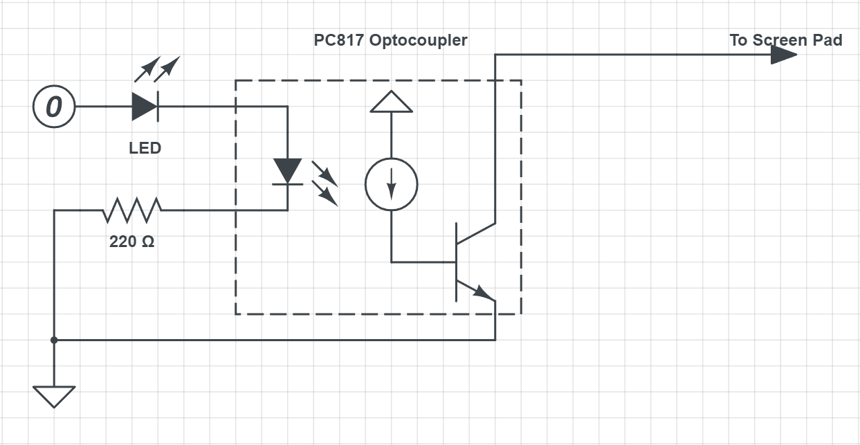
When the GPIO is high, the optocoupler switch is closed, and the electrode is connected to the ground, thereby simulating the pressed state.
Optocouplers are similar to LEDs and require a current limiting resistor in series. For example, the Forward Voltage of the PC817 I use is 1.2V and the current is 20mA. And the GPIO output of Arduino is 5V, by calculation we need to connect a resistor of about 190Ω in series. (What, you said I also connected an LED in series? Whatever, it’s not impossible to use)
Arduino Control Program
Arduino provides an IDE very simply, you can start programming by plugging in the USB of the development board. You can first follow Arduino’s standard tutorial Blink to familiarize yourself with the environment. When the program is uploaded to the development board, you don’t need an IDE. The PC will communicate via USB to the Arduino UART serial port. The code for the Arduino part is as follows:
1 |
void setup () { |
Is it very simple? Here, the serial port of the development board is initialized first, and some GPIOs are used as outputs. Then we define a communication protocol: HIG00 and LOW00 to control the high and low levels of GPIO. Note that the development board will send an OK message immediately after initialization. This is because the Arduino UNO will restart when the serial port is connected. This OK message can let the PC know that the development board is ready.
PC side
The pySerial package can be used on the PC side. When the development board is connected to a PC or Mac, it will be displayed as a COM* or /dev/tty* device. pySerial also has serial.tools.list_ports.comports() API to list all serial devices, we can find Arduino by some conditions:
https://github.com/binux/cat-planet-bot/blob/main/arduino.py
In the code I also implemented some helper functions such as throttle_press and autorelease and recorded the pressed state of each pin. These are just for convenience, not necessary, the serial port rate is completely sufficient to send each command directly, and I did not feel any delay in my tests.
More?
Just plug in more optocouplers and Arduino GPIO connections on the breadboard, and make more electrodes to support multi-touch. However, it is clear that this number is limited. And there is no way to change the click position, nor to swipe. So is there a solution? I have some ideas here:
First, the number of electrodes can be increased so as to cover the entire screen, and then the capacitance changes of each point can be controlled by partitions on the screen. The idea is described in this paper , but I didn’t find a finished product.
Another more feasible solution is to achieve full-screen coverage by mechanically controlling the stylus. For example, retrofitting a 3D printer, replacing the nozzle with a stylus, simulates clicking through the precise 3-axis movement of the 3D printer. The advantage of this solution is that the 3D printer is a very cheap finished product, eliminating the cost of purchasing scattered parts, and the firmware of many 3D printers is open source and can be easily operated through G-code .
Summarize
At this point, we have opened up the physical touch from PC to tablet. Using these things, you can develop some fixed automation scripts. For example, every time the following script is executed, it automatically presses +10 99 times and then buys:
In use, there are some experiences that affect the success rate of touch:
- After installing the electrodes, the screen needs to be turned off and on again. (The patch just installed, whether it is grounded or not, will be detected as pressed. Restarting the screen can reset this state to raised, so that the capacitance changed when grounded will be detected as pressed.)
- Connecting the tablet to a power source works even better. (This grounds the tablet, similar to how you would hold the tablet. But it doesn’t need to be connected to the Arduino.)
- I put a resistor between the electrode and ground, so the length of the wire doesn’t matter. There is no need to worry about capacitance caused by too long wires.
This article is reprinted from: https://binux.blog/2022/08/cat-planet-bot-part-1-touch-simulation/
This site is for inclusion only, and the copyright belongs to the original author.