Original link: https://blog.vvzero.com/2023/06/30/deep-into-RC-plane-s-servo-control-and-PWM/
The reason is this, some time ago, I started to play tracked vehicles and fixed-wing model aircraft at the same time. The power of the tracked vehicle is a DC motor plus a drive board, PWM modulation, and a 0-100% duty cycle to control the motor from stationary to full speed.
As for model airplanes, although I started to get in touch with them ten years ago, I have always played on the surface, as long as I can move. To play model airplanes, you must have a remote control and a receiver. The receiver also outputs PWM signals. You can control its movement within a specified angle range by connecting the steering gear, and you can control the motor speed by connecting the ESC.
So, I took it for granted that the aircraft model receiver It should also output a PWM signal with a duty cycle of 0-100%. 0 is a limit angle of the servo, 50% is the middle position, and 100% is another limit angle.
But the fact is not, I connected the drive plate of the crawler to the receiver of the model aircraft, no matter how I push and pull the joystick, the crawler always moves at a very low speed.
This aroused my curiosity.
Let’s take a brief look at the PWM signal graph of the aircraft model receiver
If you don’t have an oscilloscope at hand, just take a simple logic analyzer to deal with it:
I only measure 1 channel of data (usually the aileron/roll channel).
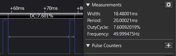
Here’s the joystick at the midpoint:
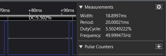
Joystick on the far left:
Joystick on the far right:
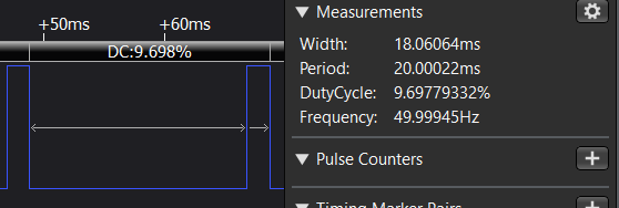
That’s funny, the duty cycle is always around 5%~10%. It shows that the PWM signal of the remote control of the model aircraft must not simply rely on the duty cycle to control the steering gear. Otherwise, leaving such a large space of 10%-100% unused is a bit wasteful.
The true interpretation of the PWM signal of the aircraft model
I checked a lot of forums, and at first it was weird that they (like this one ) basically only talk about PWM with a pulse length of 1-2ms and a frequency of “typically” 50Hz, but hardly anything about the duty cycle.
I watched it for a while and suddenly woke up, because isn’t PWM originally called “pulse width modulation”? It’s just that I used it to adjust the light and control the motor before, so I paid attention to the duty cycle, but the PWM itself should pay attention to the “width”.
So, just like the answer here , the aircraft model servo itself does not pay attention to the duty cycle, but only pays attention to how long the high level is in each cycle. 1ms represents the minimum angle, 2ms is the maximum angle, and 1.5ms is the median.
Because the general frequency is 50Hz, that is, the period is 20ms, so the duty cycle seems to be 5%-10%.
more explanation
As for why 50Hz is chosen, the explanation is: this frequency is just the working frequency of the steering gear, and the steering gear should operate according to this cycle. If it is too fast, the steering will be overwhelmed, and if it is too slow, the response will be slow.
There is also a 200Hz servo, but the pulse width is also 1-2ms, so the duty cycle becomes 20%-40%.
Of course, some servos use pulse widths in the range of 0.5-1ms and 2-2.5ms to achieve greater steering volume.
For the ESC, the signal is the same, it is very convenient to use the signal of the servo.
Also why choose 1-2ms? Because the remote control was stipulated in this way a long time ago, so I won’t say much.
This article is transferred from: https://blog.vvzero.com/2023/06/30/deep-into-RC-plane-s-servo-control-and-PWM/
This site is only for collection, and the copyright belongs to the original author.