Original link: https://www.luozhiyun.com/archives/687
Please declare the source for reprinting~, this article was published on luozhiyun’s blog: https://www.luozhiyun.com/archives/687
The first time I knew VXLAN was when I saw that the network plug-in called flannel used in k8s has a VXLAN mode, which implements the Overlay Network (overlay network) and can connect all containers together. So in this article, let’s take a look at how VXLAN connects the network between different containers.
Overview
Before looking at VXLAN, let’s take a look at its predecessor VLAN. The full name of VLAN is “Virtual Local Area Network”, which is a layer 2 (data link layer) network used to divide broadcast domains, because with the increase of computers, if there is only one broadcast domain, it will There are a large number of broadcast frames (such as ARP request, DHCP, RIP will generate broadcast frames) forwarded to all clients in the same network.
This results in unnecessary waste. On the one hand, the broadcast information consumes the bandwidth of the entire network; on the other hand, the computer receiving the broadcast information also consumes a part of the CPU time to process it. It causes a lot of unnecessary consumption of network bandwidth and CPU computing power.
In this context, VLAN technology emerged. This technology can divide a LAN into multiple logical VLANs, each VLAN is a broadcast domain, and the communication between hosts in a VLAN is the same as in a LAN, but the VLANs cannot communicate directly, and broadcast packets are transmitted. Restricted to one VLAN. As shown below.
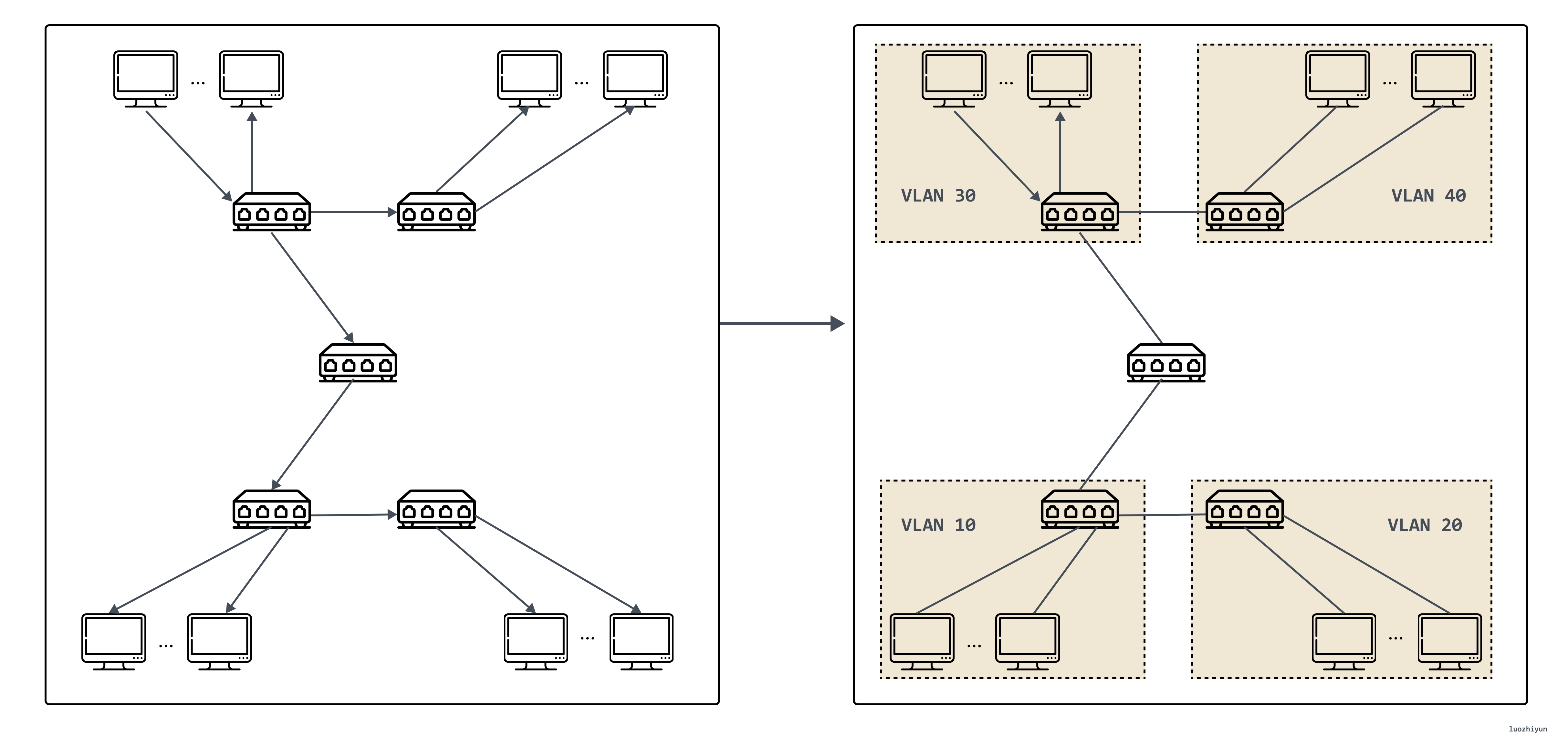
However, VLAN has two obvious defects. The first defect lies in the design of VLAN Tag. The 802.1Q specification that defines VLAN was proposed in 1998, and only 32 Bits of storage space is reserved for VLAN Tag, of which only 12 Bits can be used. Used to store VLAN IDs. When the cloud computing data center appears, even without considering the requirements of virtualization, there may be tens of thousands or even hundreds of thousands of physical devices that need to be assigned IPs, so 4096 VLANs are definitely not enough.
The second flaw of VLAN is that it is a layer-2 network technology, but information can only be transmitted between two independent data centers through a layer-3 network. With the development and popularization of cloud computing, many businesses need to operate across data centers, so data Passing VLAN tags between centers is a more troublesome thing; and in a virtual network, a physical opportunity has multiple containers, and the number of containers increases by orders of magnitude compared with VMs. Each virtual machine has an independent IP address and MAC address, so the pressure on the switch is doubled.
Based on the above reasons, VXLAN is about to come out.
VXLAN protocol
Protocol message
VXLAN (Virtual eXtensible LAN) virtual extensible local area network adopts L2 over L4 (MAC in UDP) packet encapsulation mode, and puts the Ethernet frame originally transmitted in the second layer into the packet of the fourth layer UDP protocol, and adds its own definition. VXLAN Header. There is a 24 Bits VLAN ID directly in the VXLAN Header, which can also store 16.77 million different values. VXLAN allows the Layer 2 network to expand within the scope of Layer 3, and is no longer limited by the transmission between data centers. VXLAN works on the Layer 2 network (IP network layer), and VXLAN can be deployed as long as the network is reachable at Layer 3 (which can communicate with each other through IP). The entire packet structure of VXLAN is shown in the figure:
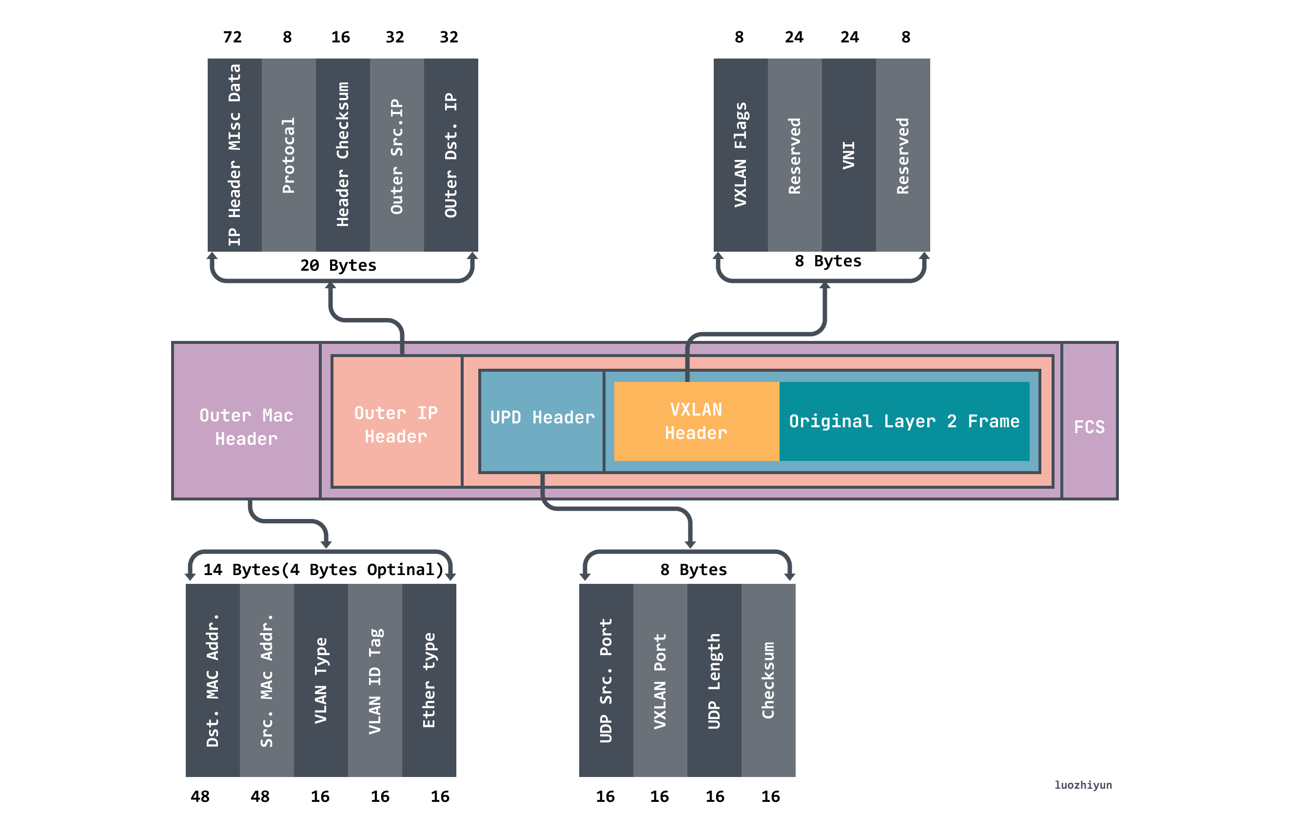
In the figure above, we can see that the VXLAN message wraps the original Original Layer2 Frame:
- The VXLAN Header is 8 bytes, including the 24Byte VNI field, which is used to define different tenants in the VXLAN network, and can store 16.77 million different values;
- UDP Header, in which the VXLAN header and the original Ethernet frame are used as UDP data together. The destination port number (VXLAN Port) in the header is fixed as 4789, and the source port is randomly assigned according to the flow (the hash operation is performed by MAC, IP, and the four-layer port number), This can better do ECMP. ;
- Outer IP Header encapsulates the outer IP header, which encapsulates the destination IP address and source IP address, where IP refers to the IP address of the host;
- Outer MAC Header encapsulates the outer Ethernet header, encapsulates the source MAC address and the destination MAC address, where the MAC address refers to the host MAC address;
working model
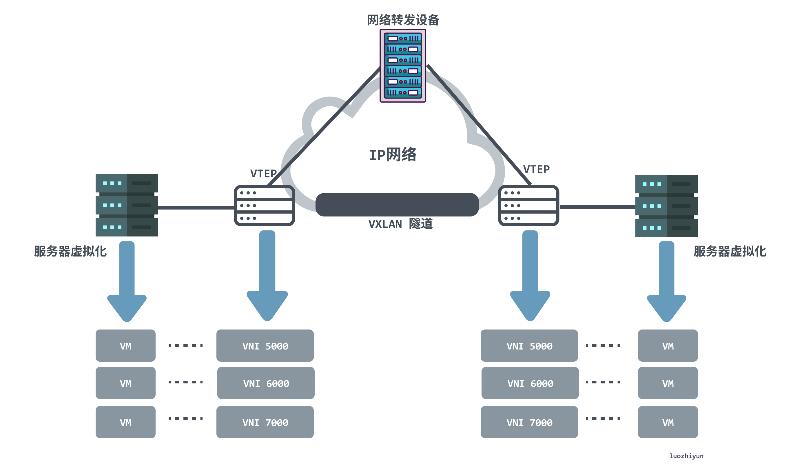
From the VXLAN network network model in the above figure, we can find that the following components appear in the VXLAN network:
- VTEP (VXLAN Tunnel Endpoints, VXLAN Tunnel Endpoints): The edge device of the VXLAN network is the start and end point of the VXLAN tunnel. It is responsible for the packetization and depacketization of VXLAN protocol packets, that is, the packet header of the VTEP communication is encapsulated in the virtual packet. . . VTEP can be a network device (such as a switch) or a machine (such as a host in a virtualized cluster);
- VNI (VXLAN Network Identifier): As mentioned above, the VLAN in the Ethernet data frame only occupies 12 bits of space, which makes the isolation capability of the VLAN ineffective in the data center network. The emergence of VNI is designed to solve this problem. Generally, each VNI corresponds to one tenant , and it is a 24-bit integer, which means that a public cloud built with VXLAN can theoretically support up to 16.77 million tenants ;
- VXLAN tunnel: Tunnel is a logical concept, and there is no specific physical entity to correspond to in the VXLAN model. The tunnel can be regarded as a kind of virtual channel. The two sides of VXLAN communication (the virtual machine in the figure) think that they are communicating directly and do not know the existence of the underlying network. On the whole, each VXLAN network seems to build a separate communication channel, that is, a tunnel, for the communicating virtual machines;
communication process
In a VXLAN network, a VTEP may have multiple tunnels. Before a VTEP communicates, it will determine the target VTEP address by querying the forwarding table FDB. The forwarding table FDB is used to store the MAC address of the remote virtual machine/container, the remote VTEP IP, And the mapping relationship of VNI, and the forwarding table is constructed by flooding and learning mechanism. Traffic whose destination MAC address does not exist in the forwarding table is called unknown unicast. The VXLAN specification requires flooding using IP multicast to send packets to all VTEPs except the source VTEP. When the destination VTEP sends back a response packet, the source VTEP learns the mapping relationship between MAC address, VNI and VTEP and adds it to the forwarding table.
Let’s take a look at the first communication process to see how VTEP learns:
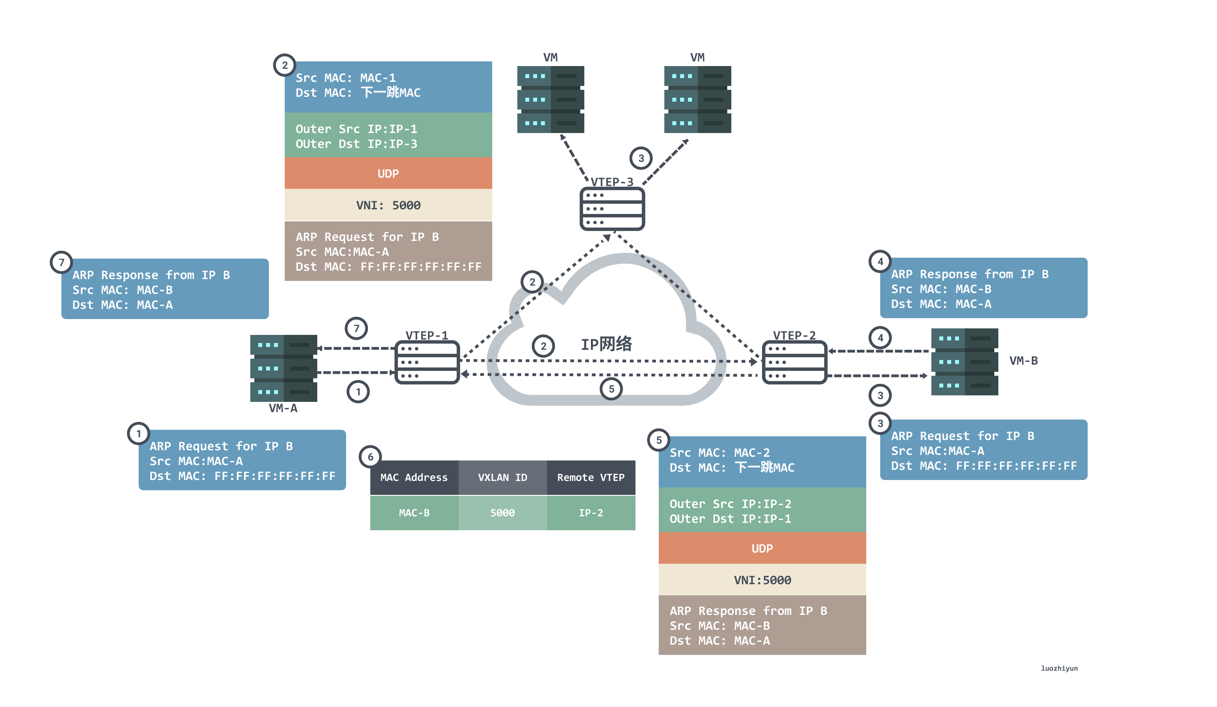
- Since this is the first communication, VM-A does not have the MAC address of VM-B, so an ARP broadcast message is sent to request the MAC address of VM-B. VM-A sends an ARP broadcast packet with source MAC as VM-B, destination MAC as full F, source IP as IP-A, and destination IP as IP-B, requesting the MAC address of VM-B;
- After receiving the ARP request, VTEP-1 determines that the packet needs to enter the VXLAN tunnel according to the configuration on the Layer 2 sub-interface. VTEP-1 will encapsulate the packet, the outer source IP address of the encapsulation is the IP address of the local VTEP (VTEP-1), and the outer destination IP address is the IP address of the peer VTEP (VTEP-2 and VTEP-3). ;The outer source MAC address is the MAC address of the local VTEP, and the outer destination MAC address is the MAC address of the next hop device in the network to the destination IP;
- After the packets reach VTEP-2 and VTEP-3, VTEP decapsulates the packets to obtain the original packets sent by VM-A. Then VTEP-2 and VTEP-3 process the packets according to the configurations on the Layer 2 sub-interfaces and broadcast them in the corresponding Layer 2 domains. After VM-B and VM-C receive the ARP request, they compare whether the destination IP address in the packet is the local IP address. VM-C finds that the destination IP is not the local IP, so it discards the packet; VM-B finds that the destination IP is the local IP, and responds to the ARP request;
- VM-B will perform ARP reply packets as unicast packets according to the requested ARP packets, the source MAC of the packets is MAC-B, the destination MAC is MAC-A, the source IP is IP-B, and the destination IP is IP-A;
- After receiving the ARP reply packet sent by VM-B, VTEP-2 identifies the VNI to which the packet belongs, and VTEP-2 encapsulates the packet. The outer source IP address of the encapsulation is the IP address of the local VTEP (VTEP-2), the outer destination IP address is the IP address of the peer VTEP (VTEP-1); the outer source MAC address is the MAC address of the local VTEP, and The outer destination MAC address is the MAC address of the next hop device in the network to the destination IP;
- After the packet reaches VTEP-1, VTEP-1 decapsulates the packet to obtain the original packet sent by VM_B. At the same time, VTEP-1 learns the corresponding relationship between the MAC address of VM_B, VNI and the IP address (IP-2) of the remote VTEP, and records it in the local MAC table. After that, VTEP-1 sends the decapsulated packet to VM-A;
- At this point, VM-A has received an ARP broadcast message in response to the MAC address of VM-B;
In addition to the above multicast learning method to obtain the mapping relationship of MAC <--> VNI <--> VTEP IP , there is another way, that is, the distributed control center.
For example, the MAC address of VTEP in Flannel’s VXLAN mode network is not learned through multicast, but is synchronized through apiserver (or etcd). When each node creates a Flannel, each node will report its VTEP information to the apiserver, and the apiserver will then synchronize to the listener (Flanneld) on each node that is watching the node api. After Flanneld gets the update message, it will pass the netlink. It is sent to the kernel, and the FDB (query forwarding table) table entry is updated, thus achieving the synchronization of the entire cluster. This apiserver plays the role of a distributed control center, and it is no longer necessary to send redundant requests to access the network to obtain the corresponding mapping information.
one example
Next, let’s make a VXLAN network by ourselves, and then capture the packets to see if it is consistent with the conclusion we have described in the long discussion above. It should be noted that when experimenting on your own virtual machine, in order to avoid unnecessary trouble, remember to turn off the firewall. The centos command is: systemctl stop firewalld
Next, we plan to use docker to conduct experiments. The idea is to create a VXLAN interface on each of the two container hosts, and connect the VXLAN interface to the port of the docker bridge, as shown in the following figure:
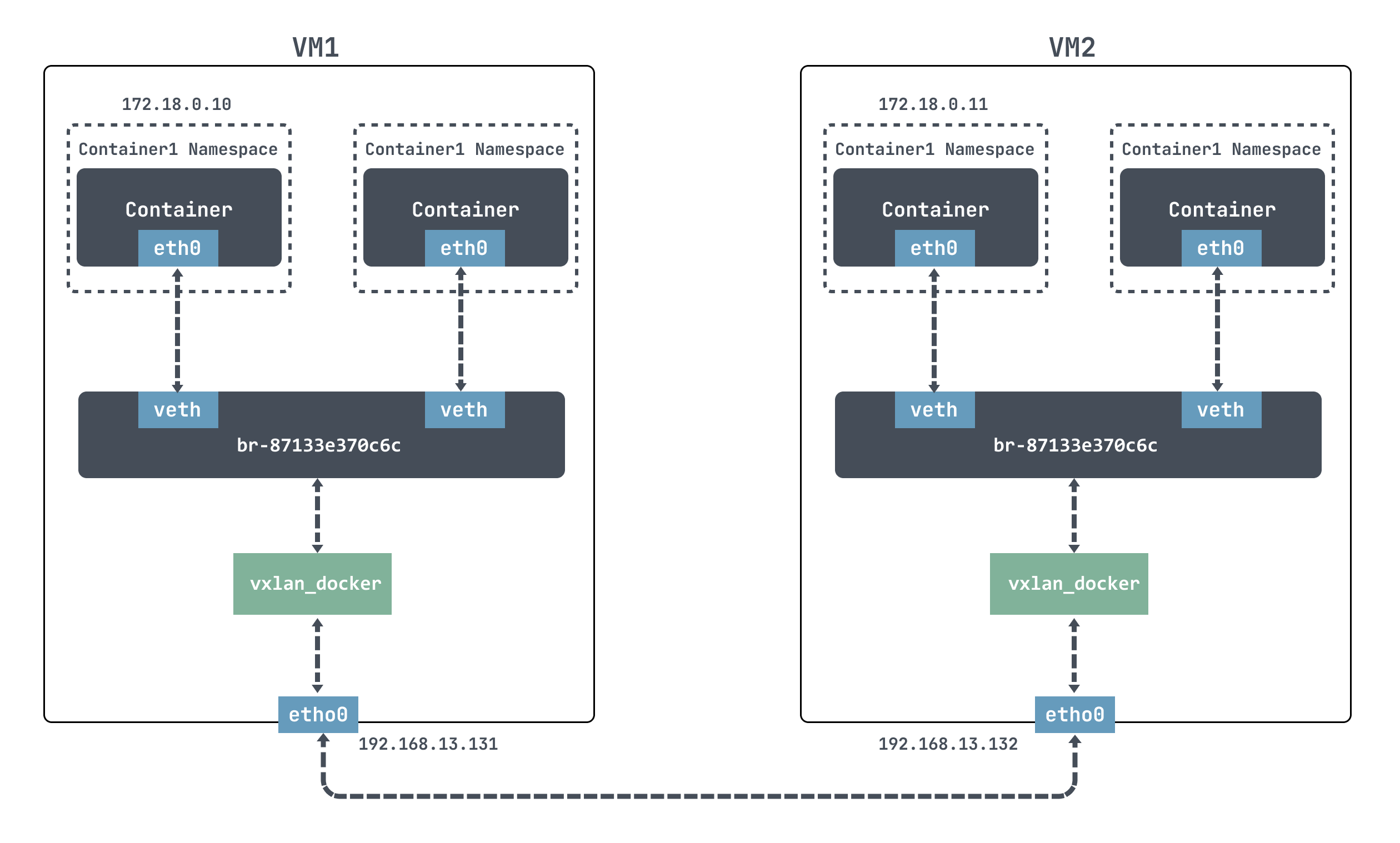
For docker, it is impossible to communicate directly across nodes. We use VXLAN here to simulate cross-node communication.
Docker uses the 172.17.0.0/16 network segment by default, and the IP address of the docker container will be allocated from 172.17.0.2. In order to use the -ip parameter to customize the IP address function, you need to create a custom network first, specifying the network segment 172.18.0.0/16.
[root@localhost ~]# docker network create --subnet 172.18.0.0/16 mynetwork ## mynetwork 新的bridge网络被创建[root@localhost ~]# docker network ls NETWORK ID NAME DRIVER SCOPE eb07bfe03ee3 bridge bridge local 7014433d34cf host host local 87133e370c6c mynetwork bridge local 82472e531205 none null local
We can also see that docker created a new bridge for our new network:
[root@localhost ~]# brctl show bridge name bridge id STP enabled interfaces br-87133e370c6c 8000.0242233b251a no veth385f866 vxlan_docker docker0 8000.024213087f4b no
Create a new container as follows:
## VM1 [root@localhost ~]# docker run -itd --net mynetwork --ip 172.18.0.10 centos ## VM2 [root@localhost ~]# docker run -itd --net mynetwork --ip 172.18.0.11 centos --net指定自定义网络--ip指定IP地址centos指定image
Although we have created the network above, we cannot communicate directly when we go in:
[root@localhost ~]# docker exec -it 5a2e519610bb /bin/bash [root@5a2e519610bb /]# ping 172.18.0.11 PING 172.18.0.11 (172.18.0.11) 56(84) bytes of data. From 172.18.0.10 icmp_seq=1 Destination Host Unreachable --- 172.18.0.11 ping statistics --- 11 packets transmitted, 0 received, +8 errors, 100% packet loss, time 10007ms pipe 4
Next, we create a VXLAN interface on each of the two container hosts, and connect the VXLAN interface to the port of the docker bridge:
## VM1 [root@localhost ~]# ip link add vxlan_docker type vxlan id 200 remote 192.168.13.132 dstport 4789 dev ens33 [root@localhost ~]# ip link set vxlan_docker up [root@localhost ~]# brctl addif br-87133e370c6c vxlan_docker ## VM2 [root@localhost ~]# ip link add vxlan_docker type vxlan id 200 remote 192.168.13.131 dstport 4789 dev ens33 [root@localhost ~]# ip link set vxlan_docker up [root@localhost ~]# brctl addif br-26d918129b18 vxlan_docker
Above, we used ip link add to create VXLAN network interfaces with VNI 200 for VM1 and VM2 respectively, named vxlan_docker; and then use brctl addif to connect the newly created VXLAN interface vxlan_docker to the docker bridge.
Then we entered the container and found that we could ping:
[root@5a2e519610bb /]# ping 172.18.0.11 PING 172.18.0.11 (172.18.0.11) 56(84) bytes of data. 64 bytes from 172.18.0.11: icmp_seq=1 ttl=64 time=1.14 ms 64 bytes from 172.18.0.11: icmp_seq=2 ttl=64 time=0.620 ms ^C --- 172.18.0.11 ping statistics --- 2 packets transmitted, 2 received, 0% packet loss, time 1002ms rtt min/avg/max/mdev = 0.620/0.879/1.139/0.261 ms
Let’s take a look at the packet capture on the host machine:
[root@localhost ~]# tcpdump -i ens33 host 192.168.13.131 -s0 -v -w vxlan_vni_1.pcap
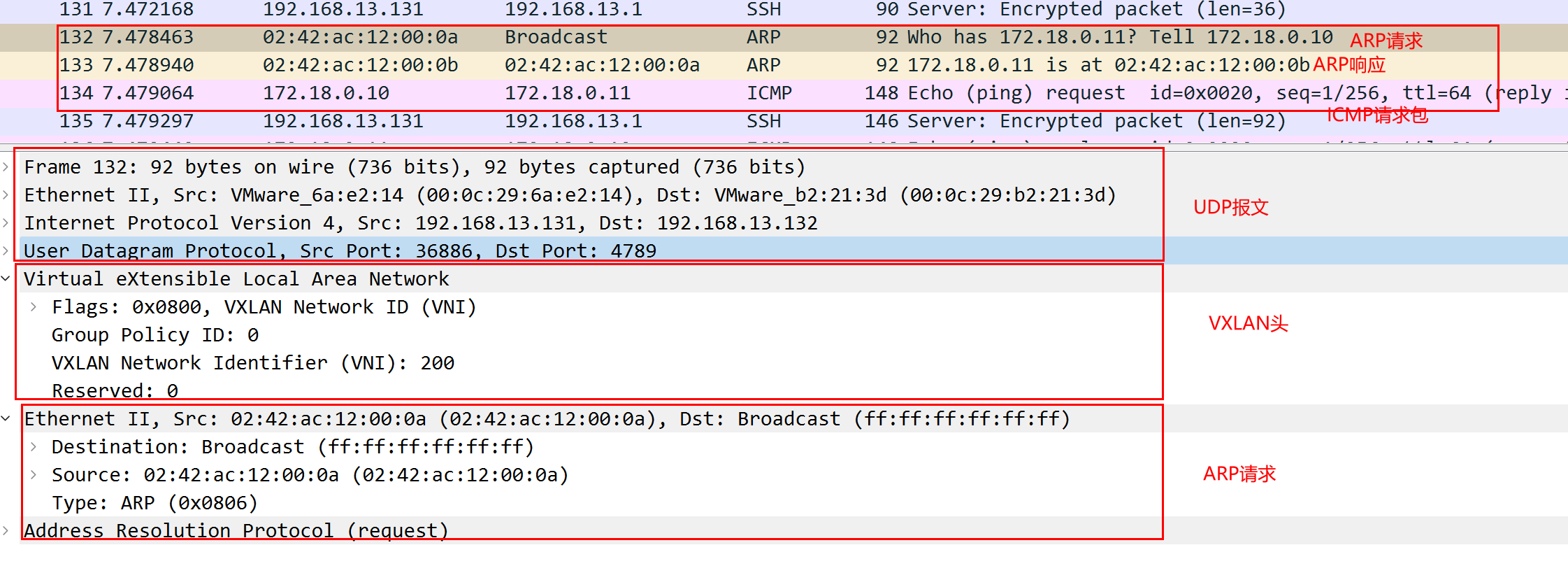
As we can see above, the first is to send an ARP request to obtain a MAC address, the outer layer is a UDP packet, the destination port is 4789, and the destination IP is the IP of the host VM2; the VXLAN packet header VNI is 200; the source MAC address of the ARP request is The container MAC address of the message sent in VM1, the destination address is not obtained, it is ff:ff:ff:ff:ff:ff ;
After receiving the return packet, 172.18.0.11 replies to the ARP response packet to inform the MAC address that the address is 02:42:ac:12:00:0b , and then the ICMP packet can be sent normally.
Summarize
In this article, we will start with the introduction of VLAN to describe the disadvantages of VLAN and why there is VXLAN. Then I talked about how the protocol packets of VXLAN are encapsulated, what is the overall working model, and the VXLAN communication process is familiar with how it works. Finally, I used an example to actually implement the interaction between containers on two nodes. communication. I believe that here, you should have a lot of understanding of VXLAN.
material
https://zhuanlan.zhihu.com/p/109349917
https://zhuanlan.zhihu.com/p/35616289
https://forum.huawei.com/enterprise/zh/thread-334207.html
http://icyfenix.cn/immutable-infrastructure/network/linux-vnet.html
https://www.ciscolive.com/c/dam/r/ciscolive/emea/docs/2019/pdf/DEVWKS-1445.pdf
http://just4coding.com/2017/05/21/vxlan/
https://www.linuxidc.com/Linux/2019-03/157820.htm
https://zhuanlan.zhihu.com/p/130277008
https://juejin.cn/post/6994825163757846565
https://ieevee.com/tech/2017/08/12/k8s-flannel-src.html

The VXLAN protocol of cloud native virtual network first appeared on luozhiyun`s Blog .
This article is reproduced from: https://www.luozhiyun.com/archives/687
This site is for inclusion only, and the copyright belongs to the original author.